In the summer of 1942, with the US invasion of North Africa on the horizon, and the British, of course, pretty much involved in the desert for a while, the US Army’s Ordnance Branch diverted some of its attention to the question of desert operations. Deserts tend to lack good terrain reference points, are often a tad warm, tend to have very long lines of visibility, and are really not massively conducive parts of the world for easy widespread maneuver. (I have often wondered when was the last time the US Army taught any of its troops how to use a sextant, in case GPS went offline in the deserts of Kuwait. Most of my troopers, when I asked, had no idea what a sextant even was)
Surely there could be a technical solution to the problem, and so Ordnance Branch set about trying to “desertise” an M4A1. Officially, “The purpose of this special equipment is to render the tank more valuable as a reconnaissance vehicle in desert operation or in operation over other suitable terrain”
As a result, a number of components were brought together.
Four of the five headlights.
Firstly, for night driving, infra-red equipment. An infra-red telescope had been tested in Sept 1940, to determine the ability to detect vehicles driving around with infra-red headlights, obviously there was a perceived need for such a thing, and the infra-red equipment was given a preliminary test back then. Nearly two years later, however, there may have been some improvements.
The majority of the time spend on this test vehicle was in the installation and adjusting of the equipment necessary. Five airplane landing lamps (4x 450 watt, 1x 600 watt) were used, requiring nearly 3,000 watts of power. As a result, the 1,500 watt generator originally mounted on M4A1 had to be replaced with a much larger unit manufactured by the Waukesha Motor Company. This thus required a major change in the tank’s electrical system, requiring a new regulator, filter and fuel system.
In addition to the lamps, of course, one needed the viewing device, which slipped neatly into the hatch periscope mount.
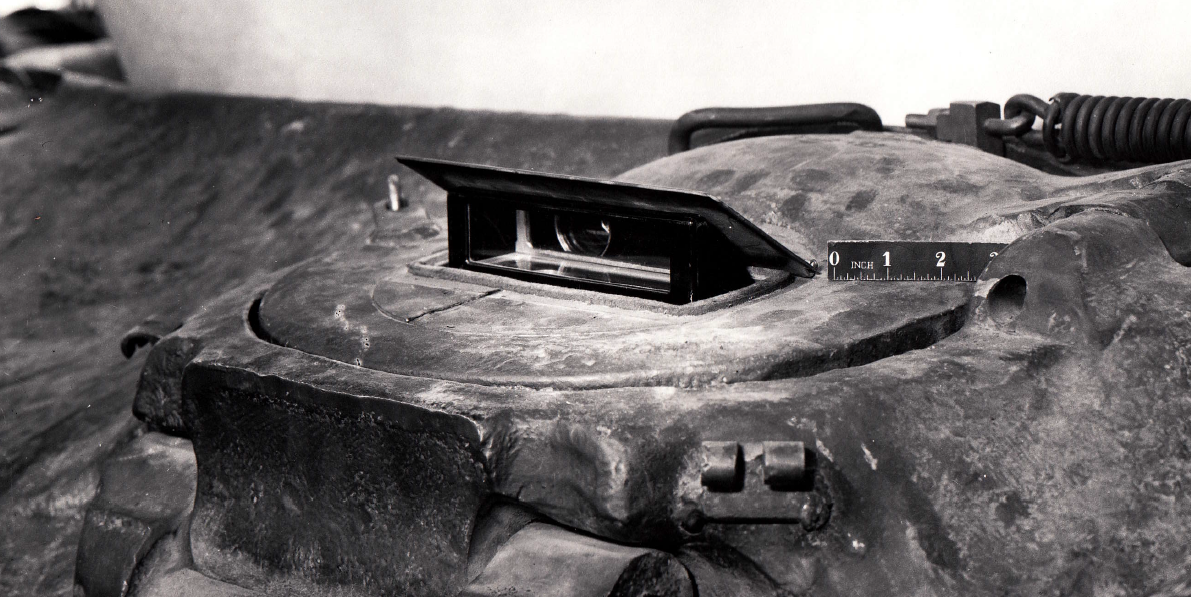
The interior of this consisted mainly of an evacuated tube containing a semi-transparant photo-cathode on which a real image of infra-red rays was case by the primary lens system. Electrons emitted by infra-red impingement on the photocathode were accelerated and focused by suitable anodes, and directed onto a flurouescent screen at the opposite end of the tube. (I don’t understand a word of this, but just in case someone finds it interesting…) The image was then viewed through an eyepiece and lens system.
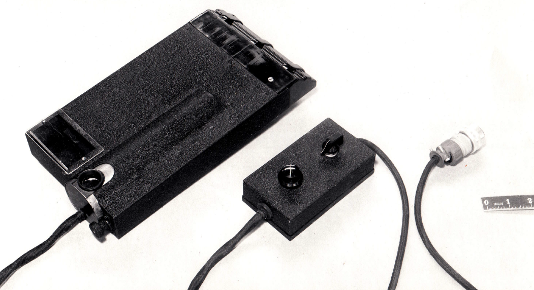
Power supplies were needed for the 5,000 volt anode voltage to the viewing tubes. One power supply could provide power for up to three viewers, so one was used for the driver and assistant driver, and another for the commander and loader. Total battery input for those was 5.4amps at 12V.
Once installed, the system was thus tested. “Innumerable difficulties were encountered with magnetic distortion in the image tubes, eye strain, and failures of the viewing equipment due to its fragility. It was apparent that much improvement can be made in the definition of the devices since some were much better than others due to better construction in the optical lens systems. In general, the light sources with Corning Glass Company infra-red filters were satisfactory.”
When they actually got the things to work, the results were as follows:
A vehicle similar to a Medium Tank may be driven over average smooth terrain at speeds from 15-20mph by means of infra-red lighting in total darkness.
It is extremely difficult to negotiate rough terrain, and especially heavy underbrush, by means of infra-red lighting [Chieftain: This may be due to the lack of depth perception from only one image. An issue unresolved even today in many ways]
Continued observation through the viewing devices may easily cause eye strain and resultant blurring to the operator.
Viewing devices and light sources submitted to this station by the National Defense Research Committee are by no means rugged enough for tank use.
The electrical input of approximately 3,000 watts required by the light sources is excessive, and greatly exceeds the available power in present Medium Tanks.
Even with a sky glow enough to permit driving along a road or on a smooth surface, the infra-red lighting is a definite aid in driving over very rough terrain, but only when extreme caution is exercised.
Thus it was recommended that further development be done on the viewing devices to improve their definition and sensitivity as well as ruggedness, and also that the efficiency and ruggedness of the light sources also be improved.
During the tests of the infra-red viewing devices, it was found that the loss of dark adaptation by the driver due to looking at illuminated areas such as instrument lights, flashlight etc caused much difficulty in driving the vehicle. As long as the instrument lights and all other interior light was eliminated, dark adaptation was easily maintained and driving was far easier. For this reason a small ultra-violet lamp with suitable filter was installed to cause the instrument markings and controls, which had been painted with Continental Lithograph Company fluorescent paint, to stand out better. The setup worked, but was not considered sufficiently rugged for tank use.
Of course, it’s only dark for part of the time. In the daytime, the problem is still light, just too much of it. Tanks, even today, tend not to have air conditioning, and it can get kindof warm. As a result, they painted the tank with an infra-red reflecting paint, developed by the Arco Manufacturing Company of Cleveland, OH. The colour was practically identical to the standard Army olive drab, and the manufacturer claimed the reflection of 45% of all infra-red radiation from the sun impinging upon the vehicle. They threw some thermometers into the tank, and sat back to watch the results.
It turned out that it dropped the ambient temperature inside the vehicle by about 6 degrees Fahrenheit. As a result, Ordnance suggested that the paint be considered for all vehicles preparing for operation in regions where excessive temperatures prevail. As I’ve never heard of this paint outside of this report, I have no idea if it ever was implemented.
We’re not done yet, though.
Sandshields were next to be added to the configuration. The effectiveness at keeping the sand down was not tested, but it was observed that the devices greatly hampered the vehicle’s operation in deep mud or rough terrain, and was very easily torn off under those conditions.
Lastly, the Recording Odograph.
This was a device which would map the course of a vehicle. As opposed to today’s inertial navigation systems, basically, it’s reverse dead-reckoning. It used a magnetic compass to indicate the direction of travel, and a ‘take-off’ from the speedometer to indicate the distance travelled. [Chieftain: People keep mocking the concept of using a magnetic compass on a tank. If you know what you are doing, or if the compass is designed for it, the effect of the metal on the tank can be negated]. The odograph consisted of three units: The compass uinit, the integrating and graphing unit, and the power unit.
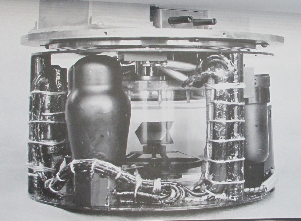
The compass unit contained a turntable mounting a light source, two photo-electric cells, and to Thyratron tubes. Inside the turntable was a compass bowl and card. On the card was mounted a mirror. When the mirror was exactly opposite the light source, the light would be reflected back and there would be no response. When the mirror was given an angular displacement the light reflected to one of the photo-electric cells placed to the right or the left of the light source. Light incident upon the photo-electric cell actuated the appropriate Thyratron tube and the discharge interpreted to drive the turntable to the right or to the left in accordance in accordance with the displacement of the angular mirror on the compass card. Thus the turntable followed the compass card and obtained its driving power through a shaft from the integrating and graphing unit. The integrating and graphing unit mounted a pencil which was driven laterally and longitudinally by two independent and concurrent drives. The speed of the drive was controlled by the speed of the rotation of the speedometer cable. The direction of the drive was controlled by the position of the turntable in the compass unit. Within the integrating and graphing unit was a device to alter the speed of the drive and thus provide a choice in the scale of the resulting map.
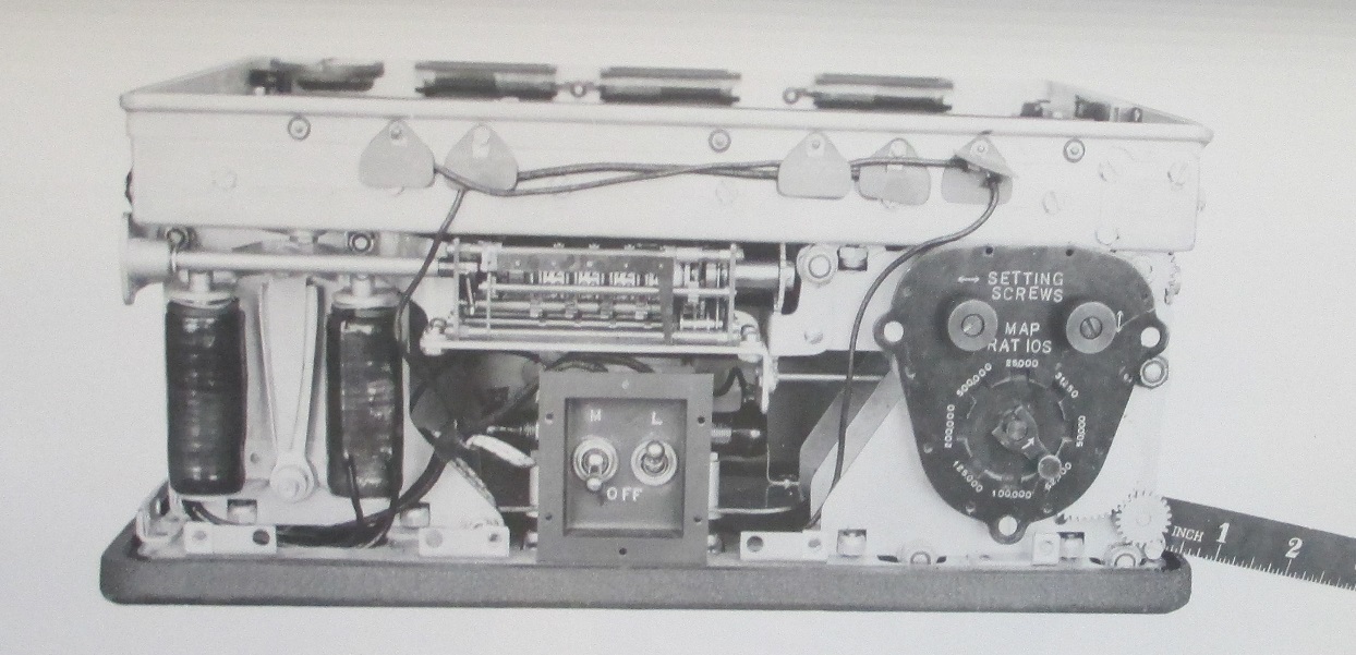
I&G Unit
Two designs of the I&G unit existed, one by the Monroe Calculating Machine Company, and the other by International Business Machines. The MCM version only permitted a limited number of map scales by shifting gears, the IBM one wasn’t present for the tests, but was supposed to permit infinitesimally variable map scales.
The development of the equipment was carried on by the Engineer Board in Fort Belvoir, in conjunction with the NDRC. The equipment was being tooled for use primarily in ¼ ton trucks and certain larger reconnaissance vehicles.
Although it was possible to calibrate the compass for the tank, certain modificiations still needed to be made in order to prevent the tank’s operation from adjusting the calibration. For example, the gear shift lever had to be changed with one made of brass. Compensation for generator charging currents had to be made by inserting a shunt in the line and taking off a proportional current for electric compensation coils. As a result, as power was used in the different devices around the tank, the compensating coils drew a proportion of this power in order to provide a counteracting magnetic field. Calibration of these compensating techniques themselves took a very long time, as it was almost impossible to visually read the compass to less than one degree. Therfore it was necessary to drive the vehicle in a known direction, and compare the record on the odograph, then adjust off that. It was hoped that future designs of odograph would make possible much more rapid compensation.
It was concluded that:
The design of the complete equipment represented a well-developed stage and that reminaing changes in the design were minor in character, providing mainly for greater convenience in adjustment and use.
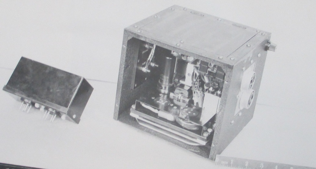
Power unit
The power unit was satisfactory in performance, but improvements could be made in sturdiness and compactness.
The compass unit, being a hand-made design, was essentially satisfactory except that the Thyratron tubes mounted on the turntable need to be shock mounted to prevent more frequent failures.
The entire system operated as it was expected to operate, but magnetic disturbances in the tank made it difficult to maintain a compensation accurate enough to give all-round accuracy of the recording odograph as close as one part in a hundred.
Overall, these were some very interesting attempts at solving the problems of fighting in the desert, though obviously the technology was just a tad ahead of its time.
Bob... you're up.
Incidentally, I've set up a streaming channel on Twitch. My Facebook page remains criminally unliked, however. I feel unloved... Maybe I should ask Bob for a hug.
